I started this project because I like building things with my hands and I thought I might learn a few things as well as play some video games eventually. Well, this weekend I decided that I might at some point want to use my control panels with my computer since they are better than any computer control panel you could buy. My design uses a standard 15 pin serial connector which is the same one that is standard on pc's. There is a difference though as I learned a few years back when I was writing my own computer games in Turbo Pascal. The pc joystick port supports two analog joysticks with two buttons each. An arcade joystick is digital (there are four switches indicating each of: up, down, left, right), so the problem is how do you make the digital stick look like an analog stick. It is not really as complicated as it sounds. There are three positions we have to indicate for each axis on the joystick. For the x-axis these are: Left, Center, and Right. For the y-axis they are: Up, Center, and Down. In a pc joystick there are two variable resistors; one for the x-axis and one for the y-axis. Let's focus on the y-axis for now. When the joystick is moved all the way up, the resistance is 0k. When centered, it is usually around 50k. When all the way to the down, it is about 100k. I wasn't quite sure how to simulate this with a digital stick until I found the plans on Mark's pages.
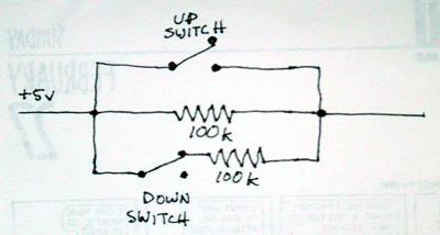
You can take a look at his diagram, or look at my sketch of one axis below. My plans are slightly different as I opted to use all 100k resistors but you get the same result once you have calibrated it on your computer.
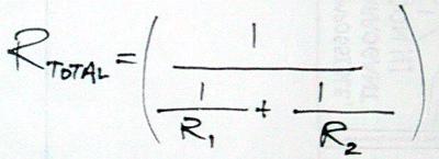
Here is a quick opportunity to learn about resistors. This circuit is a good demonstration of parallel resistors. You can calculate total resistance with the following formula:
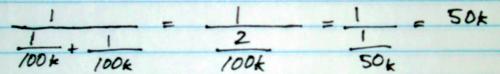
The mechanics of the arcade joystick ensures that only one of the buttons on the y-axis will be activated at a time. When the joystick is in the up position, a direct connection is made, which makes the total resistance 0k. The real trick is on the down switch. The resistor is connected to the normally closed (NC) terminal on the switch. This means that when the joystick is moved down, the connection to the second resistor is broken, increasing the total resistance. When the joystick is centered, the resistors are in parallel and the total resistance is 50k.
The x-axis can be wired up in a similar fashion. Here is the full pinout of the pc joystick connector:
| PC joystick connector | |
|---|---|
| Pin # | Function |
| 1 | +5v |
| 2 | Player 1 button 1 |
| 3 | Player 1 joystick x |
| 4 | Ground |
| 5 | Ground |
| 6 | Player 1 joystick y |
| 7 | Player 1 button 2 |
| 8 | +5v |
| 9 | +5v |
| 10 | Player 2 button 1 |
| 11 | Player 2 joystick x |
| 12 | Ground |
| 13 | Player 2 joystick y |
| 14 | Player 2 button 2 |
| 15 | +5v |
The tricky part will be figuring out how to set up the joystick so that it can be easily switched between normal arcade control panel operation and pc joystick mode.